Electrical Engineering Articles


Compensating Windings and Interpoles in DC Generator

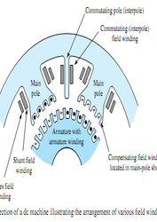
Compensating Winding and Interpoles in DC Generator In DC compound machine setup by armature current opposes magnetic field flux, this is known as armature reaction. The armature reaction has two effects (i) Demagnetizing effect and (ii) Cross magnetizing effect. Demagnetizing effect weakens the main field flux which in turn decreases the induced e.m.f (as E ∝ Ø)). To overcome this effect a few extra turns/poles are added in series to main field winding. This creates a series field which serves two purposes, (i) It helps to neutralize the demagnetizing effect of armature reaction.…

Commutation in DC Machine

One can be aware of the fact that emf induced into the rotating conductor or winding is always sinusoidal or alternating in nature. If the machine is of DC nature that is DC Generator then it is bounding for someone to convert it (sinusoidal emf) into a unidirectional emf. This process of converting AC voltage into a DC is commonly called as commutation. Hence the commutator is a device which normally acts as a rectifier and performs the process of rectification. Coil(s) current is constant and unidirectional so long as the…

Commutation In DC Machine, Generator or Motor

Commutation Definition This is the post about commutation in dc generator and dc motor. The reversal of current in the armature winding by means of commutator bar and brushes is known as commutation process. The necessity of Commutation In DC Machine Commutation serves two purposes, 1. It converts alternating current to direct current 2 It maintains rotor magnetomotive force stationary in space. The concept of Commutation in DC Machine Commutation process in DC machine can be explained by assuming commutator bar width is equal to brush width and insulation between the…

Sparking in DC Machines

Sparking in DC Machines at Brushes Poor commutation and sparking are caused by distortion of main field flux. The sparking at the brushes results in poor commutation due to the inability of the current in the short-circuited coil to reverse completely by the end of short circuit period (Usually of the order of 1/500). The main reason to delay this quick reversal is due to the production of self-induced e.m.f in the coil undergoing commutation. This self-induced e.m.f in the coil undergoing commutation is known as reactance voltage which is of Small magnitude…

Retardation Test or Running Down on D.C Machines

Retardation Test or Running Down on D.C Machines In this article, we are going to discuss retardation test on dc machines.Retardation test is also called as running down test.This is the very efficient way to find out stray losses in dc shunt motors.In this test, we get total stray losses nothing but the combination of mechanical (friction & windage) and iron losses of the machine. The circuit diagram of retardation test on dc machines shown below. A1, A2 are armature terminals. The procedure of Retardation Test on D.C Machines The main points in the retardation…

Construction of DC Machines (Motor & Generator) With Diagrams

Construction of DC Machine A Direct Current (DC) machine is an energy conversion device. It converts electrical energy to mechanical while working as a motor and the mechanical energy to electrical energy while working as the generator. Hence, it is known as electromechanical energy conversion device. It consists of stator and rotor. The stator is the assembly of main parts like the yoke, main poles, pole shoe, inter pole windings etc., and the rotor is the assembly of the armature, armature winding, commutator fan etc. Major Parts of DC Machine Construction…

Brake Test On DC Shunt Motor

Brake Test On DC Shunt Motor In this article, we are going to discuss brake test on d.c. motor.Brake test is also a method of finding the efficiency of dc motors.We took dc shunt motor as running machine. Brake test also called for direct loading test of testing the motor. Because loading will be applied directly to the shaft of the motor by means of a belt and pulley arrangement. How to conduct brake test on dc shunt motors? Test Requirements: 1. DC shunt motor 2. Water-cooled pulley  3. Spring balance The procedure of Brake Test…

4 Point Starter Working and Construction

4 Point Starter Working & Construction of Three-Point Starter In the previous post we have seen how does a 3 point starter works. There is only one difference in construction between  3 point starter and four-point starter. Here the no volt coil and field are not connected in series as in 3 point starter but the NVC is connected to the supply independently through a point called N which can be seen clearly in the below figure. Operational difference between 3 point starter and 4 point starter In 4 point starter NVC gets supply…