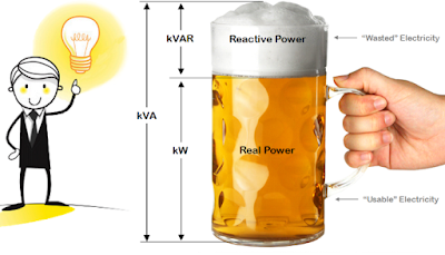
What Is Electrical Power Factor?
The cosine of the angle between voltage and current in an a.c. the circuit is known as power factor. In an a.c. circuit, there is generally a phase difference φ between voltage and current. The term cos φ is called the power factor of the circuit. If the circuit is inductive, the current lags behind the voltage and the power factor are referred to as lagging. However, in a capacitive circuit, current leads the voltage and power factor is said to be leading.
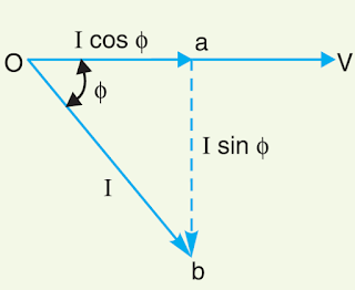
Consider an inductive circuit taking a lagging current I from supply voltage V; the angle of lag being φ. The phasor diagram of the circuit is shown in fig. The circuit current I can be resolved into two perpendicular components, namely ;
(a) I cos φ in phase with V
(b) I sin φ 90° out of phase with V
The component I cos φ is known as the active or wattful component, whereas component I sin φ is called the reactive or wattless component. The reactive component is a measure of the power factor. If the reactive component is small, the phase angle φ is small and hence power factor cos φ will be high. Therefore, a circuit having small reactive current (i.e., I sin φ) will have high power factor and vice-versa. It may be noted that value of power factor can never be more than unity.
(i) It is a usual practice to attach the word ‘lagging’ or ‘leading’ with the numerical value of power factor to signify whether the current lags or leads the voltage. Thus if the circuit has a p.f. of 0·5 and the current lags the voltage, we generally write p.f. as 0·5 lagging.
(ii) Sometimes power factor is expressed as a percentage. Thus 0·8 lagging power factor may be expressed as 80% lagging.
Power Triangle
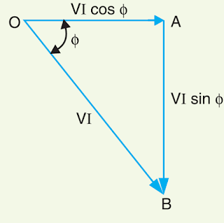
The analysis of power factor can also be made in terms of power drawn by the a.c. circuit. If each side of the current triangle oab of below figure is multiplied by voltage V, then we get the power triangle OAB shown in the figure where
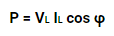
OA = VI cos φ and represents the active power in watts or kW
AB = VI sin φ and represents the reactive power in VAR or kVAR
OB = VI and represents the apparent power in VA or kVA
The following points may be noted form the power triangle :
(i) The apparent power in an a.c. the circuit has two components viz., active and reactive power at right angles to each other.
OB² = OA² + AB²
or (apparent power)² = (active power)² + (reactive power)²
or (kVA)²= (kW)² + (kVAR)²
(ii) Power factor, cos φ = OA/OB = active power/apparent power = kW/kVA
Thus the power factor of a circuit may also be defined as the ratio of active power to the apparent power. This is a perfectly general definition and can be applied to all cases, whatever be the waveform.
(iii) The lagging reactive power is responsible for the low power factor. It is clear from the power triangle that smaller the reactive power component, the higher is the power factor of the circuit.
kVAR = kVA sin φ = (kW * sin φ)/cos φ
∴ kVAR = kW tan φ
(iv) For leading currents, the power triangle becomes reversed. This fact provides a key to the power factor improvement. If a device taking leading reactive power (e.g. capacitor) is connected in parallel with the load, then the lagging reactive power of the load will be partly neutralized, thus improving the power factor of the load.
(v) The power factor of a circuit can be defined in one of the following three ways :
(a) Power factor = cos φ = cosine of the angle between V and I
(b) Power factor = R/Z= Resistance/Impedance
(c) Power factor = VI/(VI * cosφ) = Active power/Apparent Power
(vi) The reactive power is neither consumed in the circuit nor it does any useful work. It merely flows back and forth in both directions in the circuit. A wattmeter does not measure reactive power.
Disadvantages of Low Power Factor
The power factor plays an important role in a.c. circuits, since power consumed, depends upon this
factor.
It is clear from above that for fixed power and voltage, the load current is inversely proportional to the power factor. Lower the power factor, higher is the load current and vice-versa. A power factor less than unity results in the following disadvantages :
(i) Large kVA rating of equipment. The electrical machinery (e.g., alternators, transformers, switchgear) is always rated in kVA.
Now, kVA = kW/cos φ
It is clear that kVA rating of the equipment is inversely proportional to power factor. The smaller the power factor, the larger is the kVA rating. Therefore, at low power factor, the kVA rating of the equipment has to be made more, making the equipment larger and expensive.
(ii) Greater conductor size. To transmit or distribute a fixed amount of power at constant voltage, the conductor will have to carry more current at low power factor. This necessitates large conductor size.
(iii) Large copper losses. The large current at low power factor causes more I²R losses in all the elements of the supply system. This results in poor efficiency.
(iv) Poor voltage regulation. The large current at low lagging power factor causes greater voltage drops in alternators, transformers, transmission lines, and distributors. This results in the decreased voltage available at the supply end, thus impairing the performance of utilization devices. In order to keep the receiving end voltage within permissible limits, extra equipment (i.e., voltage regulators) is required.
(v) Reduced handling capacity of the system. The lagging power factor reduces the handling capacity of all the elements of the system. It is because the reactive component of current prevents the full utilization of installed capacity. The above discussion leads to the conclusion that low power factor is an objectionable feature in the supply system.
Causes of Low Power Factor
Low power factor is undesirable from the economic point of view. Normally, the power factor of the whole load on the supply system in lower than 0·8. The following are the causes of low power factor:
(i) Most of the a.c. motors are of induction type (1φ and 3φ induction motors) which have low lagging power factor. These motors work at a power factor which is extremely small on light load (0·2 to 0·3) and rises to 0·8 or 0·9 at full load.
(ii) Arc lamps, electric discharge lamps, and industrial heating furnaces operate at low lagging power factor.
(iii) The load on the power system is varying; being high during morning and evening and low at other times. During low load period, the supply voltage is increased which increases the magnetization current. This results in the decreased power factor.
Power Factor Improvement Methods
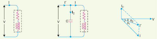
The low power factor is mainly due to the fact that most of the power loads are inductive and, therefore, take lagging currents. In order to improve the power factor, some device taking leading power should be connected in parallel with the load. One of such devices can be a capacitor. The capacitor draws a leading current and partly or completely neutralists the lagging reactive component of load current. This raises the power factor of the load.