Construction of DC Machine
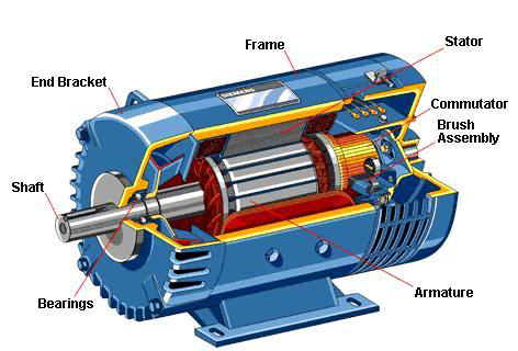
Major Parts of DC Machine Construction
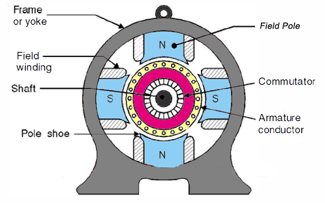
Yoke
Pole Core and Pole Shoe
Pole core is generally a solid material and pole shoe is a laminated one in small machines, but the pole shoe and pole core both are laminated made of annealed steel in modern days. The purpose of the pole core is to provide flux and to support the field windings, Whereas the pole shoe is stretched so as to provide uniform air gap along the armature core and also to provide uniform flux distribution in the air gap.
Brush and Brush Holders
Brushes are the structures placed on the rotating commutator through which the unidirectional current is to be collected. Generally, it is made of carbon, which can give smooth surface to the contacts so as to reduce the spark and wear and tear of the commutator bars. These are fixed to the stator core (yoke) by means of brush holders.
Field Windings
The field windings are wound initially on a wooden former and then installed into the pole cOre. These are generally made of low resistivity materials like copper or aluminum. There are two ways of connecting the field winding to the armature in case of the self-excited machine. They can be connected in series or shunt. If it is connected in series less numbered turns with larger cross-sectional conductors are used. If it is connected in shunt, the winding would be of large turns, whose cross-section is less, so as to withstand for the whole supply voltage.
Interpoles
These are the pole structures generally smaller than main poles and is placed in between the main poles. These windings of the inter poles are of less turns since it is connected in series with armature windings. The main purpose of these inter poles is to reduce the armature reaction, thereby reducing the sparks at the brush contacts. The polarity of the inter pole is made same as that of the main pole ahead of it in the direction of rotation.
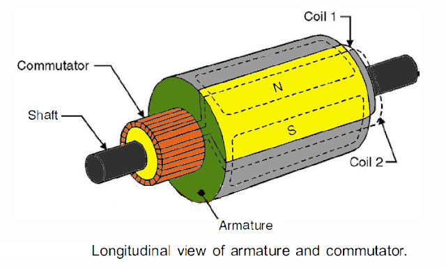
Rotor

The rotor is generally rotating part which carries the armature, armature windings and the commutator on the same shaft. The armature core is made of laminated silicon steel. The main purpose is to hold the armature windings and to provide the low reluctance path for the flux.
Commutator Construction In DC Machines
Armature Windings In DC Machines
The windings placed in the armature is called the armature windings and is generally connected in two ways,
(i) Lap windings
(ii) Wave windings.
Lap windings are preferred for higher currents and low voltage and wave windings are preferred for higher voltages and lower currents.