Instrument Transformers
Definition of Instrument Transformer
In heavy currents and high voltage a.c. circuits, the measurement can not be done by using the method of extension of ranges of low range meters by providing suitable shunts. In such conditions, specially constructed accurate ratio transformers called instrument transformers.These can he used, irrespective of the voltage and current ratings of the a.c. circuits. These transformers not only extend the range of the low range instruments but also isolate them from high current and high voltage a.c. circuits. This makes their handling very safe. These are generally classified as
(i) current transformers and (ii) potential transformers.
Current Transformers (C.T.) Construction:
The large alternating currents which can not be sensed or passed through normal ammeters and current coils of watt meters, energy meters can easily be measured by use of current transformers along with normal low range instruments.
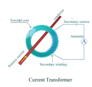
A transformer is a device which consists of two winding’s called primary and secondary. It transfers energy from one side to another with suitable change in the level of current or voltage. A current transformer basically has a primary coil of one or more turns of heavy cross-sectional area. In some, the bar carrying high current may act as a primary. This is connected in series with the line carrying high current.
The secondary of the transformer is made up of a large number of turns of fine wire having small cross-sectional area. This is usually rated for 5 A. This is connected to the coil of normal range ammeter. Through this ammeter we can note down the value of current flowing through the secondary winding of current transformer. Symbolic representation of a current transformer is as shown in the figure.
Working of a current transformer and C.T Ratio:
A combination of current transformer and ammeter helps us to find out the higher values of current flowing through line. As discussed we step down the value of line current by increasing the turns in secondary winding. This shows that there is inverse relation between between primary and secondary current and the number of turns of primary and secondary. We connect an ammeter to the secondary winding of current transformer to get secondary current which is shown in the following figure.
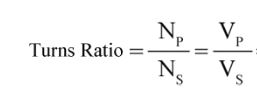
So now we can calculate the value of current through line or primary current from the C.T ratio.

Where,
Np is number turns of primary winding.
Ns is number turns of secondary winding.
Ip is current through primary winding.
Is is current through secondary winding.
Potential Transformers (P.T) Construction:
The large alternating currents which can not be sensed or passed through normal voltmeters and voltage coils of watt meters, energy meters can easily be measured by use of potential transformers along with normal low range instruments.
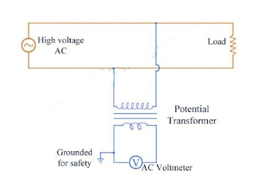
A potential transformer has two winding’s namely primary and secondary. Primary winding has large number of turns and it is connected in parallel to the line(between line and ground) whose voltage is to be measured. Now the secondary has less number of turns. This is usually rated to 110 V and is connected directly to voltmeter. Through this voltmeter we can note down the value of voltage across the secondary winding of potential transformer.Symbolic representation of a potential transformer is as shown in the figure.
Working of a potential transformer and P.T Ratio:
A combination of potential transformer and voltmeter helps us to find out the higher values of potential across the line. As discussed we step down the value of primary voltage by decreasing the turns in secondary winding. This shows that primary and secondary voltage and the number of turns of primary and secondary are directly proportional.We connect an voltmeter across the secondary winding of potential transformer to get secondary voltage which is shown in the following figure.
So we can calculate the value of line voltage or voltage across the primary of potential transformer from the P.T ratio
Where,
Np is number turns of primary winding.
Ns is number turns of secondary winding.
Ip is current through primary winding.
Is is current through secondary winding.
In this post we have learnt about instrument transformers namely current transformer and potential transformer.