In this post, we are going to learn about Direct Online Starter or DOL starter.
Why We Use Starter?
A starter is generally used to limit the high starting currents. An induction motor has high starting currents which may cause the winding’s to damage. In order to prevent this, we use starters while starting an induction motor. The direct online starter is one of the simplest motor starters which is used for starting the induction motor. This starter is generally used for starting of cage type induction motors.
Note: Starter action will be only at the start of induction motor i.e, until it gains a required amount of speed (generally until it reaches 85% of synchronous speed) after that it will be isolated from the circuit automatically by few internal actions.
Principle Of DOL Starter:
1.We start by closing the contactor and by applying the full voltage across the motor windings. This causes the motor to draw the very high amount of starting currents for a short duration.
2. Now the iron coil will get magnetized and the current will be limited to locked rotor current of the motor. Now the motor will develop locked rotor torque and accelerates to achieve full speed.
3. While it is accelerating the current will decrease slowly. The clear drop of current can be seen only after motor reaches 85% of synchronous speed.
4. Note that starting current curve depends only upon terminal voltage and design of the motor, it doesn’t depend upon the load applied on the motor.
5. Motor load only affects the time taken for the motor to accelerate to full speed but not magnitude of starting current.
6. Only if the torque developed by the induction motor with DOL starter exceeds the load torque then only induction motor accelerates to full speed if not the induction motor must be replaced with a suitable capacity induction motor which can develop torque more than the load torque.
Key point: DOL starter has maximum starting current and maximum starting torque.
Main Parts Of DOL starter:
1. Contactors and coil.
2. Overload Relay.
let us see the use of these parts in detail now.
Contactors & Coils:
The contactors that we are using are electromagnetic contactors. With the help of electromagnetic energy, they can make or break the circuit.
It consists of a coil wound on an iron core. So when the electrical energy passes through this coil the coil makes the iron gets magnetized as a result it attracts the armature and hence the circuit is made that means a closed circuit is formed. When the current interrupt the iron core gets demagnetized as a result it releases the armature this breaks the circuit. The contactor has three main normally open(NO) contacts and auxiliary contact which has lower power ratings and it can be of normally open(NO) or normally closed(NC) type.
Over Load Relay:
From the name it suggests that it is used for overload protection. Generally, overload relays have inverse-trip-time characteristics. It cannot provide protection against short circuit currents it only provides protection when the high currents are drawn for a longer period. This is the main advantage of this overload relay over fuses. As we have high inrush currents at the start of motor for a short period of time if we use a fuse it melts every time when we start a motor but this shouldn’t happen, moreover if we use high capacity fuse to prevent this it cannot sense the currents which can damage the motor winding’s.
Unlike fuse overload relay is useful in this case since it permits high currents only for short time and high inrush currents at the start of motor exist only for the shorter duration the overload relay doesn’t trip at the start. But later on when the current drawn exceeds the full load current for a longer duration then the over load relay trips the circuit. This means overload relay senses and reacts to the harmful overload currents only. We can classify overload relays based on the characters that are used to detect the overload conditions.
Types Of Over Load Relays:
There are 3 types of overload relays. They are as follows:
1. Thermal Relay:
Based on the rising temperature caused by overload currents the thermal relay trips and breaks the circuit. This can be further classified into two types namely melting alloy and bimetallic.
2. Magnetic Relay:
When the current exceeds a certain limit the coil gets magnetized which helps to trip the relay and break the circuit. It will not be affected by temperature.
3. Electronic Relay:
These are ideal relays and can trip the circuit precisely and in a fast manner. They can be installed easily.
Working With DOL Starter:
Now let us discuss the working of DOL starter or direct online starter in detail.
We can understand the working of DOL starter clearly by seeing the circuit diagram of DOL starter.
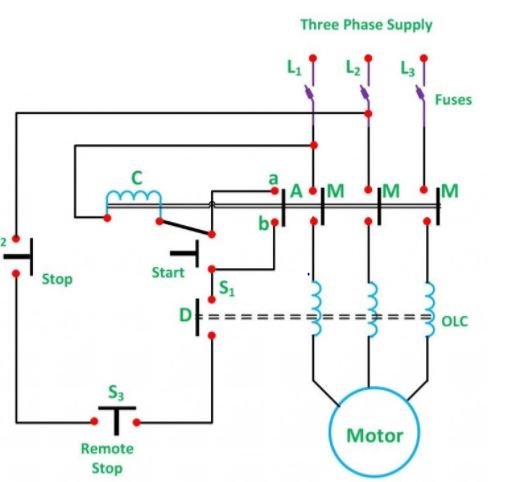
DOL Starter Circuit Diagram:
1. To switch on the induction motor first press the start push button, S1. Now the contactor gets energized from two lines L1, L2.
2. As a result, three main contacts and auxiliary contact gets closed and ab is short-circuited. So now the motor gets connected across the main supply.
3. Start button goes back due to spring action but the contactor gets energized through ab.
4. If the stop button is pressed supply through contactor is stopped and as a result, the coil gets demagnetized and the main contacts and auxiliary contacts are opened as a result induction motor is disconnected from main supply.
5. Now to start the motor again we need to push the start push button.
How Under Voltage Protection Is Done?
When the voltage falls below a certain level or when there is fail in providing supply the coil of contactor gets de-energized as a result supply to induction motor stops. In this way under voltage protection is done.
How Over Load Protection Is Done?
When there is overload the overload coils in the circuit gets energized and the normally closed coil D will change to open position, contactor coil gets de-energized which causes the supply to the induction motor to stop. In this way induction, motor winding’s are saved from burning or over heating due to overloads.
Relation Between Starting Torque And Full Load Torque Of Induction Motor:
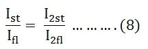
Ist be the starting current drawn from the main supply per phase.
It is the full load current drawn from the main supply per phase.
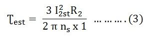
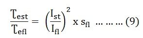
Ʈest is the starting torque.
Sfl is the slip at full load.
we know,
rotor copper loss = S x rotor input (S means slip)
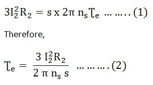
At start, S = 1, I2 = I2st, Ʈe = Ʈest.
So we get,
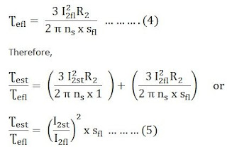
At full loads = sfl, I2 = I2fl, Ʈe = Ʈefl
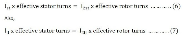
If we neglect no load current, we have
Equating 6 and 7 equations we get,
Equating 5 and 8 equations we get,
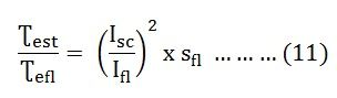
If V1 is the stator voltage per phase equivalent
Ze10 is the standstill impedance per phase of the motor referred to the stator.
Then the current at the starting is given by the equation as shown.
Starting current is equal to the short circuit current.
From equation 9 and 10 we get,
This the relation between start torque and full load torque of induction motor.
Advantages Of DOL Starter:
1. It is the simplest form of starter.
2. It is the more economical starter.
3. It gives high starting torque.
4. The control circuit is simple and can easily troubleshoot.
5.Occupies less space.
6. Easy to find fault.
Disadvantages Of DOL Starter:
1. High starting currents.
2. High starting currents of the motor cause the large voltage dip or drop of electrical supply which affects the other appliances connected to the supply.
3. High starting torque required by the load may cause increasing mechanical stresses on motor mechanical parts as well as the loads.
4. Not suitable for motors having higher ratings( above 10 KW).