In this post we are going to learn about electrical transformer.we can say transformer as static induction motor.You know why we are using AC power instead of DC power in our power system,Because of so many advantages of AC power over DC power.One of main advantages of AC supply is transformation [changing one level to another level ].This transformation is possible by a static electrical machine called transformer.
Definition of Transformer:
Transformer is an electrical device which transfers power from one circuit to another circuit without electrical coupling at constant frequency.In the transformer the total power supply is constant with negligible losses so,it is also called as constant power device.Transformer is also called as constant frequency device.
To maintain constant power at input and output side voltage and current values will changed in inverse proportional manner.i.e.,For example at input side you have 200 V,10 A.If you want 400 V at output side then current must be 5 A.So,overall power in the transformer will become constant.This is the answer you can tell who asks you “what is transformer ?“.
Construction of Transformer
Transformer consists of two coils,based on power supply primary winding and secondary winding.Based on actual construction HV(high voltage) winding and LV(low voltage) winding.This two windings are placed on a magnetic core made up of CRGO steel(latest transformers) or Silicon steel (old transformers).CRGO steel is used to reduce iron losses.Magnetic core is laminated to reduce eddy current losses.In the next post we will post a detailed information on losses in transformer.
Constructional Parts of Transformer
There are three major parts of the transformer.They are,
1.Primary Winding of transformer :- This is connected to power supply.It produces magnetic flux.
2.Magnetic Core of transformer :- This acts as a pipeline to carry the flux through it and delivers to the secondary winding.
3.Secondary Winding of transformer :- the flux, produced by primary winding, passes through the core and cuts the secondary winding.So emf will induce in the secondary winding of transformer.
3.Secondary Winding of transformer :- the flux, produced by primary winding, passes through the core and cuts the secondary winding.So emf will induce in the secondary winding of transformer.
Working Principle of Transformer
The working principle of transformer is based on Faraday’s laws of electromagnetic induction.According to Faraday’s law,whenever there is a relative space (or) time variation between magnetic field and set of conductors an emf will be induced in the conductors,vice-versa.
Another main principle of transformer working is mutual induction. According to mutual induction,current in the one coil is responsible of emf induced in another coil.
Let us understand in more easy way,assume there are two coils.Say first and second.Now we are supplying voltage to first coil,then according to Faraday’s law an alternating flux surrounding that coil.If suppose any coil present in the range of alternating flux,then this alternating flux cuts the coil.Hence emf induce in the second coil.This is the fundamental working of any transformer.The flux linkage between two coils is always constant.So transformer is also called as constant flux device.
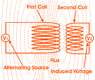
Based on number of turns in the coil emf will induce in the second coil.The transformer which is discussed above will not work practically.Because in practical applications we have to consider efficiency of transformer,losses,economical aspects.In the above figure you can find that so much flux wasted and not linked with the second coil.This is called leakage flux in the transformer.So to reduce leakage flux we use a magnetic core which gives low reluctance path for flux.We can find reduced leakage flux after placing a magnetic core.
Mathematics of Transformer
Where:
VP – is the primary voltage
VS – is the secondary voltage
NP – is the number turns of primary winding
NS – is the number of secondary winding
Φ (phi) – is the flux linkage
We heard, transformer can increase or decrease the voltage but up to what level it can increase or decrease ?.This depends on turns ratio (or) transformation ratio(denoted with n or k) of transformer.This can be defined as the ratio of number turns of primary winding to number of secondary winding (or) ratio of primary voltage to secondary voltage.
Based on the turns ratio we can classify step-up transformer or step-down transformer.n<1 for step-up,n>1 for step down transformer.
Transformer EMF Equation
Where:
ƒ – is the flux frequency in Hertz, = ω/2π
Ν – is the number of coil windings.
Φ – is the flux density in webers.