Three phase energy meter working, construction
An energy meter is used to measure the energy consumed in the kilowatt hours. This is used in each and every house and industry for calculating the energy consumed by them. A 3-phase energy meter has same elements as in case of a single-phase energy meter. We see each of them in detail in this post.
Construction of three-phase energy meter:
A 3-phase energy meter has following systems. These systems are same for both single phase and three phase energy meters. They are:
1. Driving System.
2. Moving System.
3. Breaking System.
4.Registering or Counting System.
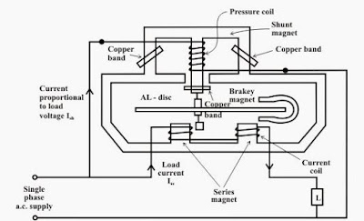
Driving System:
This consists of a coil wounded on the central limb of a shunt electromagnet which acts as pressure coil also known as voltage coil. This coil should have high inductance which means that inductance to the resistance ratio of this coil is very high. Because of this inductive nature, the current, flux will lag behind supply voltage by 90° approximately.
Copper shading bands are provided on the shunt magnet’s central limb to get 90° phase angle displacement between magnetic field set up by the shunt magnet and supply voltage. We have another series electromagnet on which current coil is wounded. This current coil is in series with the load so load current will flow through this.The flux produced by the series magnet is proportional to and in phase with the load current. The driving system of 3-phase energy meter comprises of these elements.
Moving system:
On a vertical spindle or shaft, a light rotating aluminum disc is attached. With the help of a gear arrangement, the aluminum disc is attached to the clock mechanism on the front side of the meter which helps to measure the energy consumed by the load.
Eddy currents are induced due to time-varying flux produced by series and shunt magnets. A driving torque is set up due to the interaction between these two magnetic fields and eddy currents.
Therefore the number of rotations of the disk is proportional to the energy consumed by the load in a certain time interval and is measured in kilowatt-hours (Kwh).
Breaking system:
To damp aluminum disc we keep a small permanent magnet diametrically opposite to both the ac magnets(parallel, series). Now, this disc moves in the magnet field crossing air gap. When this happens eddy currents are induced in the aluminum disc which interacts with the magnetic field and produces breaking torque.
The speed of the rotating disc can be controlled by changing the position of the brake magnet or diverting some of the flux.
Counting system:
It has a gear system to which pointer is attached. This is connected to aluminum disc which drives this pointer. This pointer moves on the dial and gives the number of times the is disc rotated.
These can be seen in the diagram given below:
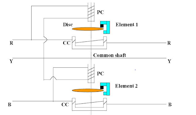
A 3-phase induction motor has same four systems but they are arranged in a different way as shown in the figure given below.
This is a two element 3-phase energy meter. On a common spindle, two discs are mounted and each disc has its own break magnet. Moving system drives a gear Each unit is provided with its own copper shading ring, shading band, friction compensator, etc., to make adjustments for obtaining the correct reading.
This gives the construction of a 3 phase energy meter.
Working on three-phase energy meter:
Now let us see how a 3 phase energy meter works.
For same power/energy, the driving torque should be equal in both elements. For adjusting torque in both the elements we have two current coils connected in phase opposition and two potential coils connected in parallel. Full load current passes through the current coil and this arrangement causes two torques to be in opposition and the disc doesn’t move if torques are equal. The magnetic shunt is adjusted if there is inequality in torques to make the disc to stand still. Before testing a 3 phase energy meter torque balance is obtained in this way.
Aluminum discs are acted upon by the two coils one is voltage coil and the other is the current coil. Voltage coil produces magnetic flux proportional to voltage and current coil produces magnetic flux proportional to current. The voltage coil field lags by 90 degrees by using a lag coil.
Due to this two torques, eddy currents are produced in the aluminum discs and discs rotate on a common shaft. Force exerted on the aluminum disc is proportional to the product of instantaneous current and voltage. To this shaft, a gear arrangement is made and a needle is attached to this gear so when discs rotate this needle moves on the dial and counts the number of rotations of the disc.
A permanent magnet is used to produce a force in opposition and proportional to the speed of the disc. When power is switched off this acts as the break and makes the disc to stop rotating instead of rotating faster. The disc rotates at a speed proportional to the power consumed.
Instantaneous power can be calculated by using formula
Pi = (3600 * N) / (T * R)
where
Pi = Real power being used at that point in time in kW
T = Time (in seconds) for the disc to rotate through the N rotations or part of a rotation
N = The Number of full rotations counted.
R = The number of revolutions per Kilowatt hour (rev/kWh) of the meter being used.
In this way, we use a three-phase energy meter to calculate the energy consumed by the load.